Intro
This part explains the various hardware upgrades we have implemented in the XXL Ultimaker. The project is build up from many smaller ones, for example the stepper motor upgrade and LED installment.
Part 1: Getting organized

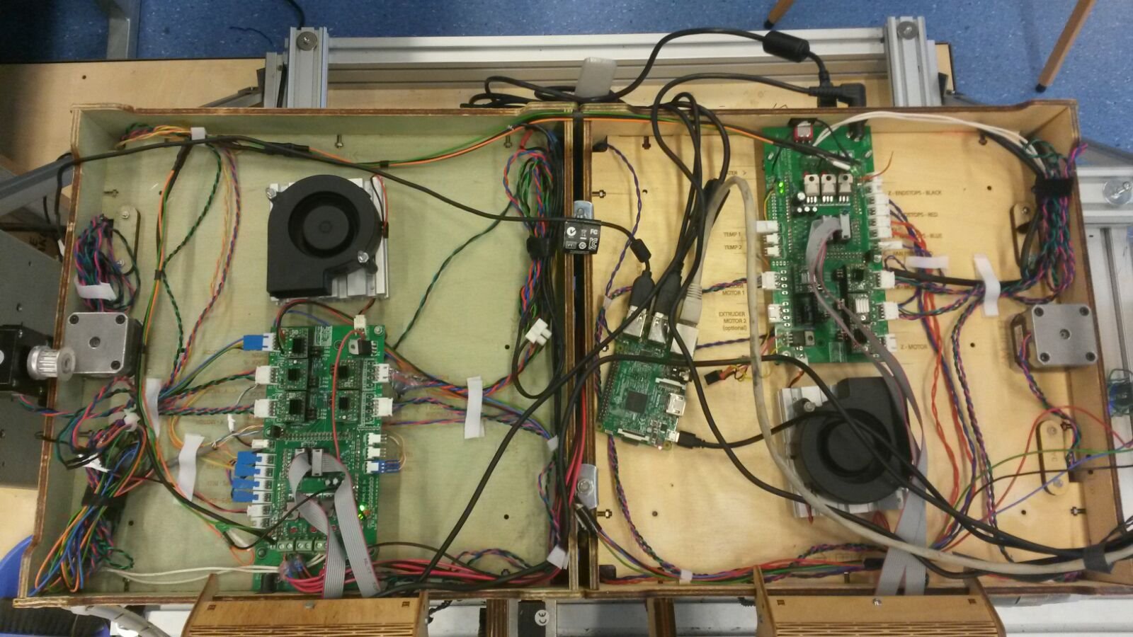
As stated before the hardware is one chaotic mess and poorly organized. The excess cables are clipped to the sides to prevent them from getting tangled in the vent. In order to create a logical and understandable appearance this has to change.
The goal is to create a logical layout of the hardware in wich the user can easily retrace a cable for possible repair or adjustments. Also does the layout contribute to our goal to create a more user-friendly design. We will accomplish this by realigning the cables along the walls and leading them straight to their connection point.
Before starting we photographed the current situation, to compare the new situation later but also to be able to review it if we need to know where one of the cables was connected. This method proved very valuable later on.
The first step in creating a simpler layout is by making a mess of it. Untying the cables and removing the current fasteners revealed the space available and the varying length of the cables. Secondly we aligned them one by one along the sides up to the point that they go straight to their connection point. Thirdly we fastened the cables with Velcro straps. The Velcro allows one to easily close and re-open the strips. For instance when a cable needs to be replaced, the other cables will still be held in place by the Velcro while you make the repairs. The Velcro is fastened with two sided tape, we chose this application method because it allows for an invisible seam and thus gives a more simplistic appearance. Last but not least we cleaned out the dust gathered on the hardware.
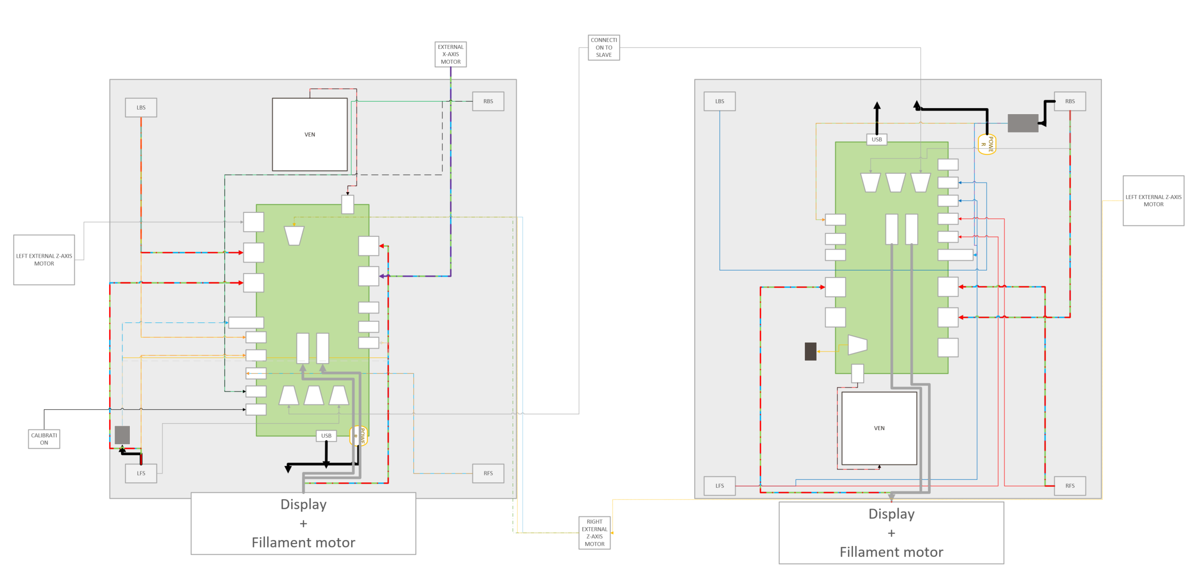
The final step in creating a fully user friendly hardware by sketching up the hardware layout as can be seen in the visuals. This map does not include the main power cord, LED cables and USB port for the Raspberry Pi since these elements are subjected to change.
Part 2: Installing the new Raspberry Pi
To get a new Raspberry Pi (so we can try and play around with some plugins) to work, it had to be connected to the TU network. But in order to login, there had to be some sort of internet browser installed on the Pi. We installed a text oriented web browser, Lynx, from our home network. Once back at the TU, we were able to login with the use of this browser. Now the Raspberry Pi had internet access in TU environment. Because the Pi was already flashed with Octoprint, the first instance (master) of the server started as soon as the Pi booted. To get the second instance (slave) running, a SSH connection (via Putty) with the Raspberry Pi was established. In this environment, we used the following command:
/home/pi/oprint/bin/python /home/pi/oprint/bin/octoprint serve –host=145.94.58.112 –port=5001 –basedir ~/.octoprint2&
This command starts the second instance of the server on port 5001 via Python. Once the new Pi was up and running, we installed a few new plugins and tested printing. Added plugins to octoprint:
Printer statistics
Title status
LED
displayZ
Part 3: Placing the RasberryPi and adding the covers
The final step in organizing the hardware is to place the RaspberryPi and applying the covers, for more information view project Cover Works and Cover Works 2.0. Easterly said than done.

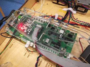
First of all the Raspberry Pi needs to fit at an open place in the cover, this was already had since there are so many cables and the Pi needs a lot of space. Also it is very unhandy if the breadboard is placed over other cables. Furthermore, the Pi comes with several cables that all need to be fitted and neatly led through the cover. Namely the ethernet cable, power supply, protuding SD card and several cables to pilot it for start up. From this came idea for the Raspberry’s casing and the slight adjustments in design, read more about this in project Cover Works 2.0. Eventually the Pi is placed in the slave near the central cable exit.
The vent cover came with the same trouble. First of all the vents are currently placed on top of a improvised aluminium profile, so they blow the air at the right height over the breadboard. The cover provides fastening points for the vent, thus the aluminium profile is unnecessary and can be disposed of. Second the overall fastening of the vent needed some special attention. The screw threat pillars that hold the breadboard and cover up, were to short. This resulted in tailoring the new screw threat and fastening for the cover. The end result is amazing, the translucent cover adds to the experience of seeing what is really happening, for example the communication between master and slave.
A final addition to the hardware is the central ‘tree root’ of cables leading upward from the XXL Ultimaker. The cables all come toghether in the Brand sign and are held together by a cable spine, as it is called. The only default is that when the Ultimaker moves upwards the cable root curls up on top of the Ultimaker cover. This can do no harm, after all it is the reason we designed the top cover. However a future project could be to design a system inside the Brand sign that rolls up the cables when the Ultimaker moves, this installment can be easily added to the structure. The new appearance is much more calm and clear to understand.
Part 4: Motor upgrade
In the middle of our project the new Ultimaker arrived. This new model was ordered to replace the oldest (green, master) Ultimaker, mainly because of the color and better stepper motors.
For this project we only installed the new motors. The effect of the new parts was immediately visible when printing, it went smoother and the motor compartment got less overheated.
The reason we did not replace any other parts is because it is not necessary. The exterior color is not disturbing at the moment, it only looks a little damaged. These small places can be easily repaired with al little fluid wood and paint. Furthermore, replacing the exterior would require us to disassemble the entire Ultimaker. This action would consume to much time that we can better spent on other projects. Secondly the new hardware cannot pilot 4 different motor compartments at the same time, the old one can. These motor are needed to move the various axis and provide the material flow. Thirdly, the entire calibration would have to be redone, costing to much time and effort. To conclude replacing the entire Ultimaker is not necessary at the moment but can be a future project.
Part 5: Adding the LED’s
As mentioned in project ‘Light it up!’ we added several LED cables to various places with different purposes. The installment of the cables was a bit of a struggle, since there is only one output port to operate the LED’s with. This was solved by soldering the cables together as one and connect them all to the same output. Because this hot bed is a heater, and therefore potentially dangerous, a certain safety to that particular pin was applied. To bypass this safety feature, it had to be removed from the ‘sensitive pins’ list.
This solution had one unexpected benefit, namely that all the LED strips are lit at once. The default of this instalment is that when you use multicolour LED cables you might want to adjust the color for each LED strip separately. We already thought of a solution: expanding the breadboard with more output pin’s. This is relatively simple and quickly done by connecting the extra output points to the main board. However since we only use white LED strips to light the print surface this is not a necessity for now.
The LED cables are led along the sides to uphold a clear overview of the hardware layout. The LED strips are further led in between the two Ultimakers after which they split into two groups: two to the left printer and two to the right. The strips are secured against the top of the Ultimaker with tape.
Part 6: Heater fail
At the start of the second week we ran into the problem where the slave printer gave a “Heating fail” error when trying to preheat the nozzle. After considerabele amount of time it turned out te be a matter of pressing the switch at the back of the Ultimaker… Sometimes things are just not as complicated as one might think they are.